LabVIEW Implementation Process
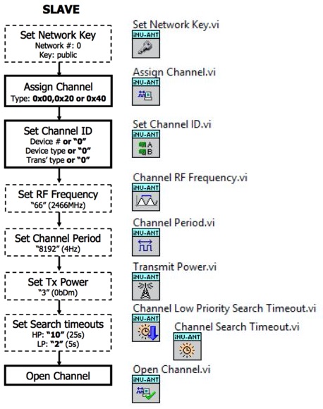
Opening a Channel – Slave
A ‘Slave’ is any device that is used to view the information from a sensor, a sensor is classed as a ‘Master’ device.
To connect as a slave the process shown in the flow diagram to the left must be followed. This diagram is taken from the ANT Message Protocol and Usage document, p.21.
To the right of the flow diagram is the equivalent process using the ANT Toolkit for LabVIEW. These VIs can be found in the ‘Config Message VIs’ folder and the ‘Control Message VIs’ folder of the ANT+ Toolkit category in the Functions pallet. The inputs to these VIs can be set according to the flow diagram, or to different settings depending on the requirements.
All of these settings have default values, so if they are not explicitly set they will use these values. The default values are shown in the flow diagram.
Extra settings can be made at this stage, but are not essential. Examples of additional settings are: Set Encryption Key, Configuring the Frequency Agility and Setting a 128-bit Network Key. All of these extra settings can be found in the ANT Message Protocol and Usage document in section 9.
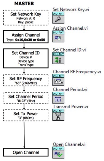
Opening a Channel – Master
A ‘Master’ is any device that is used as a sensor (such as a MOXY Muscle Oxygen sensor) that sends data to a display, a display is classed as a ‘Slave’ device.
To connect as a slave the process shown in the flow diagram to the left must be followed. This diagram is taken from the ANT Message Protocol and Usage document, p.21.
To the right of the flow diagram is the equivalent process using the ANT Toolkit for LabVIEW. These VIs can be found in the ‘Config Message VIs’ folder and the ‘Control Message VIs’ folder of the ANT+ Toolkit category in the Functions pallet. The inputs to these VIs can be set according to the flow diagram, or to different settings depending on the requirements. Note that the search priority is not set for the master device as it does not activly seek to connect to a slave, it simple broadcasts data even if nobody is listening.
All of these settings have default values, so if they are not explicitly set they will use these values. The default values are shown in the flow diagram.
Extra settings can be made at this stage, but are not essential. All of these extra settings can be found in the ANT Message Protocol and Usage document in section 9.
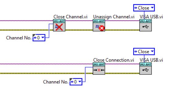
Closing a Channel
To fully close and enter a state where it is safe to remove the USB device there are 3 commands that need to be completed:
Close all Channels
Unassign all Channels
Close the VISA USB Session
When a channel is closed (using ‘Close Channel.vi’) all settings remain valid and it can be re-opened at any time using Open Channel.vi.
Once the Unassign Channel command has been sent (using ‘Unassign Channel.vi) all settings are erased and the values are rest to default. To reopen the channel one of the above sequencees must be followed.
When the channel has been successfully closed and unassigned, the VISA USB session can be stopped (using VISA USB.vi). This makes it safe to remove the ANT dongle from the USB Port.
The Close Channel and Unassign Channel VIs are contained in the ‘Close Connection’ VI, this VI also contains error checking to ensure that the connection is properly closed. See bottom of the image to the left.
Note that all channels that have been opened will need to be individually closed using this process.
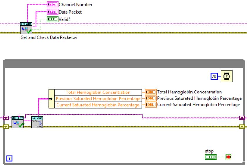
Receiving Data
Once a channel has been successfully opened it is possible for the master (the sensor) to send data to the slave (the monitor) and vice versa. In both cases this data packet will need to be received and decoded. The full data packet will be formatted according to the ANT Message Protocol and Usage document, section 7.
To receive the data packets use ‘Get and Check Data Packet.vi’ (see left, top). This VI carries out several actions:
Gets the data packet from the ANT Buffer
Checks that the data packet is correctly formatted
Verifies that the expected checksum is the same as the one in the data packet
Removes the unneeded bytes from the data packet
Separates out the actual data and the channel that this data is associated with
If the ‘Valid?’ Boolean output is FALSE then the data packet should be ignored as it failed one of the checks so cannot be guaranteed.
The Get and Check Data Packet VI can be placed inside a loop to continually receive data, as shown (see left, bottom). The Data Packet output should then be translated from the raw HEX values into usable information, in the example shown the data is converted into information according to the Muscle Oxygen Profile.
The Data Packet output is an 8 byte HEX string that is formatted according to the relevant profile description, or according to the custom format specified in the master implementation. It can be ‘decoded’ using simple string manipulation techniques contained in the standard LabVIEW Functions Pallet.